
")

Test section length 100 m
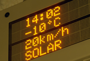
Maximum temperature gradient -45°C to +60°C
Maximum wind speed 300 km/h
Relative humidity at temperatures >10°C 10 to 98%
Solar simulation
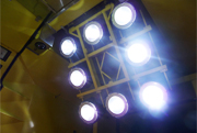
A lateral solar panel is installed in both climatic wind tunnels to simulate solar radiation on vehicle side wall and roof areas at a 30° angle of incidence. The panels are arranged to cover the roof and one side of the vehicle to ensure homogenous radiation input. The intensity can be continuously adjusted from 250 W/m² to 1000 W/m². The solar radiation panel in the large CWT is 60 m long.
Another solar panel is installed in the flow area of each test section in order to simulate solar radiation on the front parts of a vehicle, such as the driver’s cab. The panel is arranged so as not to disturb flow characteristics and can be adapted to vehicle geometries, i.e. the angle of incidence can be varied from 0° to 90°. Again, the radiation intensity can be freely adjusted from 250 W/m² to 1000 W/m².
Rain, snow and ice simulation
The simulation of snow, rain and ice plays a major role in climatic testing along with temperature, humidity and solar radiation. The climatic wind tunnels are equipped with various devices specially designed for this purpose.
A spray rig can be inserted into both climatic wind tunnels so that the entire frontal part of the vehicle can be uniformly covered with rain, snow and ice. The ultra-fine snow and ice nozzles are designed to produce droplets down to sizes of < 20 µm (see Spray-tec droplet measuring instrument). This feature is especially important when carrying out tests for the aviation industry, where subcooled water droplets must be simulated.
Connections for individual nozzles are arranged along the test section to allow for local snow and ice application. The system can be used at air speeds of up to 160 km/h and temperatures down to -20 °C.
An additional rain rig for rain and ice tests is installed in the ceiling. It can be set to a precipitation rate of up to 80 l/(hm²) over the entire test section (in both climatic wind tunnels simultaneously). The rig sections in the tunnels are divided into segments of 15 m each, which can be activated or shut off separately.
For certain functional tests, e.g. on high-voltage disconnecting switches or current collectors, subcooled water must be used for the production of clear ice. The facility is equipped with a water cooling system and a pump unit for this purpose.
Roller dynamometer and exhaust system
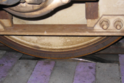
The roller dynamometer installed in the front part of the test section allows braking and traction tests to be performed on rail vehicle bogies. The roller dynamometer consists of two pairs of rollers; one roller pair can be driven or braked (power max. 850 kW), while the other roller pair is a non-driven axle with adjustable distance to the driven roller pair.
An exhaust system with two outlets located each in the ceiling and wall in the front third of the test section is designed to discharge exhaust gases from combustion engines. If one ceiling and one wall exhaust outlet is used, the exhaust air volume discharged can be adjusted from 0.32 to 3.2 kg/s at 200°C. If only one wall exhaust outlet is used an exhaust air volume of up to 0.2 kg/s at 200°C is possible.